
F1 BLARE Alarm Clock
Race Into Your Day. Formula 1 Speed Meets Embedded Precision.
A high-octane custom hardware alarm clock sculpted in the shape of a Formula 1 racecar. Featuring a custom 2-layer KiCad PCB, Seeed XIAO ESP32-C3 microcontroller, 2.25" ST7789 TFT display, 4 Cherry MX mechanical keyboard switches, 3.3V piezo buzzer, and a custom 3D aerodynamic chassis.
Why Build a Normal Alarm Clock When You Can Build an F1 Car?
Created for the Hack Club BLARE challenge: combining the tactile feel of mechanical keyboard switches with the adrenaline of Formula 1 motorsport.
Formula 1 Cockpit on Your Desk
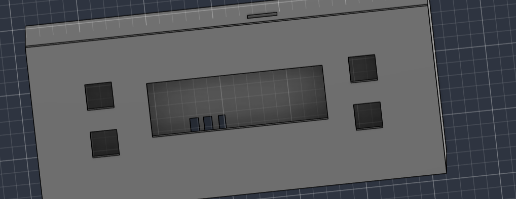
Instead of a generic rectangular clock box, the F1 car sits proudly on top of the embedded base. The vibrant ST7789 TFT display is embedded directly in the front fascia, flanked by mechanical controls.
4x Cherry MX Tactile Controls
Four mechanical keys provide satisfying tactile feedback for navigating through screens, incrementing/decrementing alarm times, and silencing the high-frequency piezo buzzer.
Full KiCad Electronic CAD
Engineered from scratch in KiCad: complete schematic design, footprint assignment, 2-layer track routing, DRC clearance checks, and 3D step model integration to fit the custom chassis.
Live In-Browser F1 BLARE Simulator
Test the embedded firmware state machine! Press the 4 Cherry MX buttons below to switch screens, change alarm times, toggle alarms, and test the piezo buzzer sound.
4x CHERRY MX TACTILE SWITCHES
Interactive Hardware ControlsComplete Bill of Materials (BOM)
All components, mechanical fasteners, and electronic modules required to construct the F1 BLARE alarm clock.
| Qty | Component Name | Designation / Specs | Function |
|---|---|---|---|
| 1x | Seeed XIAO ESP32-C3 | RISC-V 160MHz, Wi-Fi / BLE | Main compute core, SPI display driver & GPIO controller |
| 4x | Cherry MX-Style Switches | Mechanical Key Switches | Front fascia tactile control (+, Set/Stop, -, Mode) |
| 1x | 2.25" TFT Color Display | ST7789 IPS, 240x240 RGB | High-contrast dashboard & alarm status visualization |
| 1x | 3.3V Piezo Buzzer | Through-hole, High-dB | Audible alarm notification acoustic emitter |
| 1x | 8-Pin Female Header | 2.54mm Pitch Connector | Direct modular interconnect for TFT ribbon breakout |
| 8x | Jumper Wires | Female-to-Female Ribbon | Internal signal routing between board and panel |
| 8x | M3 Heatset Inserts | Brass Threaded Inserts | Melted into 3D print for rigid, reusable chassis joints |
| 8x | M3 Fasteners (x8 & x16) | M3x8mm & M3x16mm Screws | Secure PCB baseplate and F1 car body assembly |
| 1x | Custom F1 BLARE PCB | 2-Layer FR4, 1.6mm thickness | Custom routed motherboard designed in KiCad |
| 1x | 3D Printed F1 Body & Base | PLA / PETG F1 Aerodynamic Shell | Custom ergonomic racecar desk enclosure |
KiCad PCB Engineering & 3D Modeling
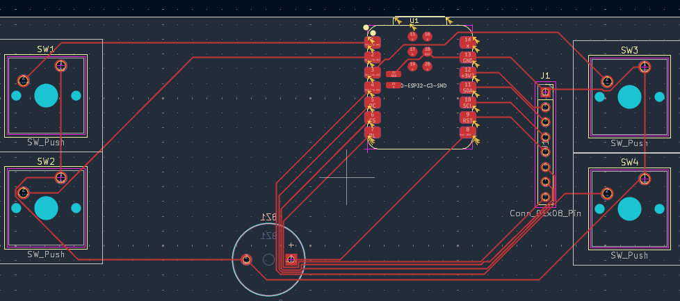
Designed to fit within the custom enclosure footprint while providing reliable mechanical switch anchoring and clean SPI signal traces.
PCB DESIGN HIGHLIGHTS
-
Schematic & Pinout Assignment:
Pinouts mapped efficiently on Seeed XIAO ESP32-C3 to dedicate hardware SPI for ST7789 TFT display and 4 interrupt-capable GPIOs for Cherry MX switches. -
Design Rule Checks (DRC):
Passed comprehensive DRC checks for minimum trace clearance, annular rings, and power trace widths for the 3.3V buzzer. -
Enclosure Alignment:
Mounting holes placed at exact coordinates matching the 3D-printed chassis heatset inserts for perfect structural alignment.
3D Aerodynamic F1 Car Enclosure
🏎 Aerodynamic Silhouette
The top shell is sculpted in the authentic proportions of a Formula 1 racecar—complete with front wing, sidepods, halo, and rear wing assembly.
🔩 Modular Base Integration
The bottom base firmly houses the custom PCB and Seeed ESP32-C3, presenting the TFT display angled ergonomically towards the user's eye level.
🔴 Heatset Insert Rigidity
M3 brass heatset inserts prevent stripped plastic threads, allowing the clock to be disassembled and reassembled repeatedly without wear.
Arduino C++ & Adafruit GFX Engine
#include <Adafruit_GFX.h>
#include <Adafruit_ST7789.h>
#include <SPI.h>

#define TFT_CS    D1
#define TFT_RST   D2
#define TFT_DC    D3
#define BUZZER_PIN D0

#define BTN_PLUS   D4
#define BTN_SET    D5
#define BTN_MINUS  D6
#define BTN_MODE   D7

Adafruit_ST7789 tft = Adafruit_ST7789(TFT_CS, TFT_DC, TFT_RST);

enum ScreenMode { MODE_CLOCK, MODE_ALARM_1, MODE_ALARM_2, MODE_ALARM_3 };
ScreenMode currentMode = MODE_CLOCK;

void setup() {
    pinMode(BUZZER_PIN, OUTPUT);
    pinMode(BTN_PLUS, INPUT_PULLUP);
    pinMode(BTN_SET, INPUT_PULLUP);
    pinMode(BTN_MINUS, INPUT_PULLUP);
    pinMode(BTN_MODE, INPUT_PULLUP);

    tft.init(240, 240);
    tft.setRotation(2);
    tft.fillScreen(0x0000);
}